 A lil' history ...
Well, if you ever had modified an
Aiptek 1,3M camera, modifying the Aiptek 1.3 SD version is almost as simple.
This webpage will be brief, in that it will show you how to fit the AipAxe R/C
switch into the Aiptek 1.3 SD camera.
OK,... so here we go...
Parts & Tools List
...
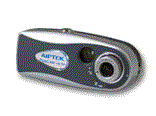
1) Aiptek 1.3
SD mega -pixel
camera (a 128M SD card is highly recommended too)
2) AipAxe R/C Switch!
3) Tiny (28+ gauge?) hookup wires
4) Razor blade or file for trimming case for servo wire
5) Soldering iron (1/16" tip) + solder
6) Snippers, pliers, tiny Philips screwdriver, Magnifying glass (if your eyes
are not up to par), etc...
7) Patience! (most important!)
Building Instructions...
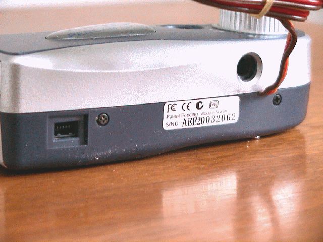 On
the Aiptek SD camera, there are two retaining screws that hold the two camera
halves together. These two small screws are located on the
bottom of the camera, where the tripod inset and USB cable connectors are
located. Remove these two screws using a small
Philips screwdriver (a magnetized one will save you lots of trouble, as it is
very easy to loose the tiny irreplaceable screws).
On
the Aiptek SD camera, there are two retaining screws that hold the two camera
halves together. These two small screws are located on the
bottom of the camera, where the tripod inset and USB cable connectors are
located. Remove these two screws using a small
Philips screwdriver (a magnetized one will save you lots of trouble, as it is
very easy to loose the tiny irreplaceable screws).
NOTE: Before removing the top case section, adjust
the lens focus such that it is set for infinity (clockwise). Remember this
as when you replace the top case section, you can be assured that the focus
setting is retained. Also, once the top case section is removed, be sure
not to touch the focus lens. Doing so will alter the correct focus and
will require unnecessary refocusing.
Once these screw are removed, rotate the top
case section off the bottom case section. It might take a bit of fussing
but for the most part, it comes off in a "snap".
(This pic to the left shows that of the camera already
modified, as you can see the switch installed)
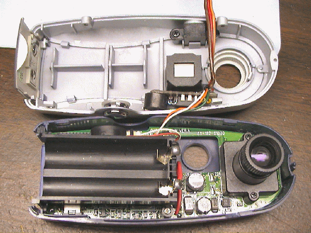
Once open, remove the two screws holding down the
battery tray (one on each side of black tray).
Removing this battery tray will gain you clear access to the USB connections and
shutter switch connection.
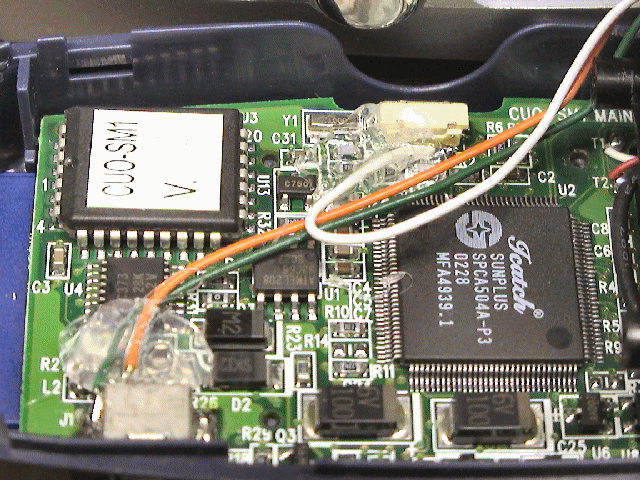
The picture to the left indicates
the location of the USB connector and the
camera's shutter switch connections. The shutter switch has two
connections, one to ground and one to the camera processor. We only need
to make a connection to the switch pin that is connected to the processor (the
pin furthest to the right, where white wire is connected to)
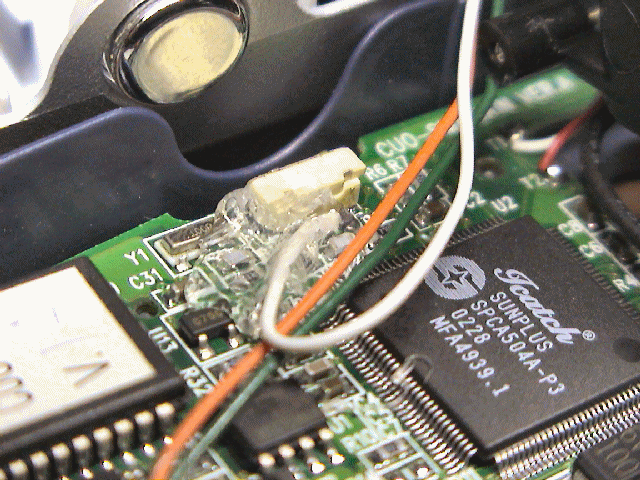 Using
a small piece of insulated wire and a small tipped soldering iron,
solder the wire to the switch connection
as shown. After soldering, you can test the connection by temporarily
installing the batteries, waiting for the camera to beep (powered and ready) and
then touching this wire to ground (the metal case part of the USB connector is fine).
If properly connected, this should force the camera to take a picture and beep.
Using
a small piece of insulated wire and a small tipped soldering iron,
solder the wire to the switch connection
as shown. After soldering, you can test the connection by temporarily
installing the batteries, waiting for the camera to beep (powered and ready) and
then touching this wire to ground (the metal case part of the USB connector is fine).
If properly connected, this should force the camera to take a picture and beep.
Next, connect two pieces of
wire to the USB connector. One wire will connect to ground (the metal
casing of the USB connector, green wire). The other connection can be a little tricky
(orange wire).
You need to make a connection to the outside pin (#1) of the USB connector.
You need to be VERY CAREFUL in making this connection as again, it can render
your camera useless. Such that you have adequate space, make the
connection to the USB pin first (then connect USB ground connection).
First, tin the end of your insulated wire and trim it such that the exposed
tinned wire is approximately 1/16". You can also dab a little flux onto
the USB pin prior to soldering. This will help facilitate the quick
soldering of the wire. Touch the tinned wire to the outside of the USB
pin, then gently apply your soldering iron to the tinned wire.
NOTE: DO NOT APPLY TOO MUCH PRESSURE TO THE WIRE/USB
CONNECTOR ! Doing so will most likely break the connection from the USB pin
to the camera board and you will then be unable to use the USB connector for
downloading pictures. Trust me,,, I have done this..... ONCE!.
Apply enough heat to the wire such the it gently connects to the
USB lead. After making this connection, you can again test the camera to
be assured it is still working properly (you might want to also check the USB
connector by attaching it to your PC and downloading pictures).
After being assured that it is connected and the camera is still
functional, make the ground connection to the USB metal case (you might have to
use some additional heat to get it to connect)... phew..... the tough part is
now done!
I usually then apply some
hot melt glue (or such) to the USB connection just to be certain that
excessive vibration does not bother the connection. I highly recommend
this step as it can not hurt. The glue will also allow you to manipulate
the wire without having to worry about breaking the connection or worse yet,
break the USB connection to the camera board.
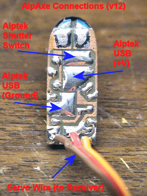
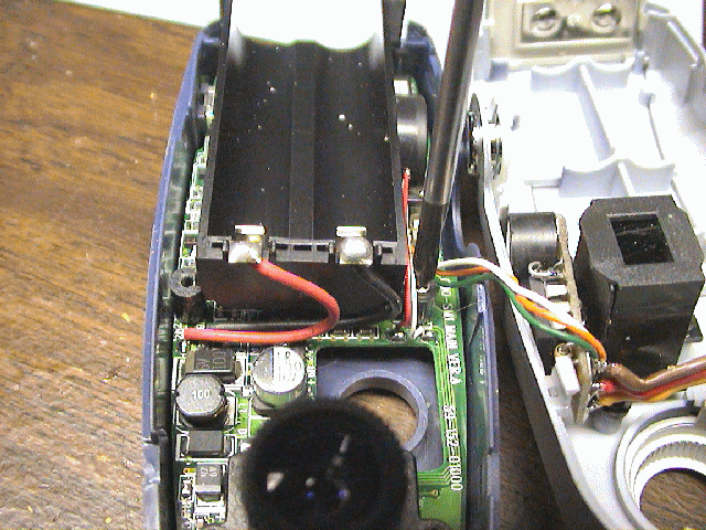
The R/C switch circuit is then
wired up to the connecting wires you just soldered. See the
attached diagram as to how to connect
these to the AipAxe switch.
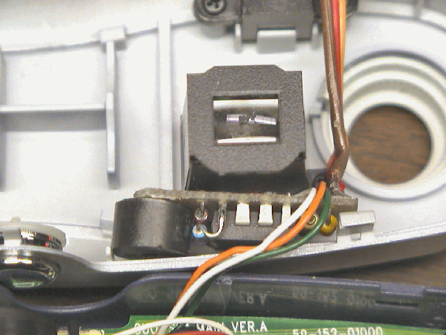
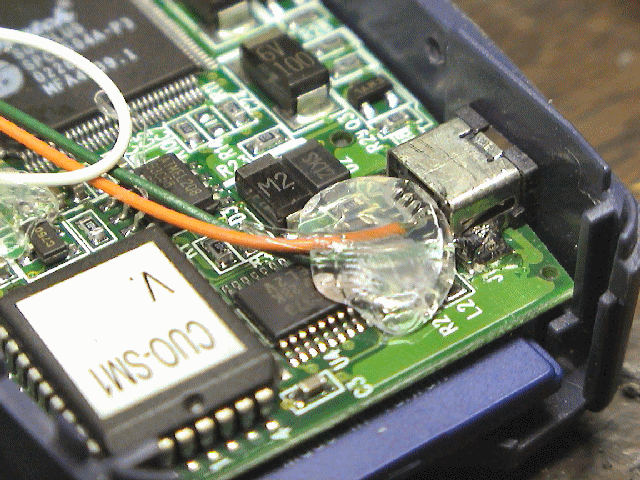
Here's another picture
showing where the R/C switch circuit is located in the camera. There's ample room
along the left side the lens, just below the shutter switch.
Route the wires carefully so that they do not get in
the way or get pinched when the camera is reassembled.
 Using a razor blade, I then
notched out a small opening in the middle case section. After this, I
reinstalled the top case section. Before installing, be sure to adjust the
silver plastic focus ring so that it is fully clockwise (focus set to infinity).
This will insure that the focus setting is correct.
Using a razor blade, I then
notched out a small opening in the middle case section. After this, I
reinstalled the top case section. Before installing, be sure to adjust the
silver plastic focus ring so that it is fully clockwise (focus set to infinity).
This will insure that the focus setting is correct.
Reinstall the case sections together and be careful
you do not pinch any wires. Replace the two tiny screws that hold the case
halves together. Also, be certain the sliding battery compartment door is
properly in place before snapping the top case onto the camera.
YOU ARE NOW DONE!
TIME TO TEST !
Testing and Operation Instructions...
 CLICK
HERE TO DOWNLOAD THE MANUAL (MS WORD)
CLICK
HERE TO DOWNLOAD THE MANUAL (MS WORD)
(THIS IS FOR THE NEWER FIRMWARE)
1. With both the transmitter
and receiver powered off, plug the camera's servo plug into the receiver channel
# to which you want to use as your shutter control. This can either be a switch
or joystick.
2. Power up the transmitter
first and position the switch or stick (corresponding to channel on receiver
which switch is connected) in the direction to which you would want to be the
OFF position (the position where no picture is taken).
3. Now power up the receiver and
you will hear the switch and Aiptek camera eventually power up (beeps).
About a second or two after that (as the circuit analyzes the receiver servo
signal), you will hear a "Ready" beep (2 low beeps then a longer high beep)
indicating that the circuit is ready for operation (no others beeps should be
heard until you take a picture).
IS THAT SIMPLE ?
4. To take a picture, move
the joystick/switch to the On position and then return it to the opposite (OFF)
position. You should hear the switch circuit output a low to high chirp, and
then quickly hear the Aiptek camera take a picture (also visible on the Aiptek
display). If the transmitter's switch/joystick if left in the ON position, the
switch circuit will make the Aiptek camera take a picture approximately every 7
seconds, until the switch/joystick is returned to the OFF position.
5. If you were to turn
off the transmitter while the receiver and camera are powered up, the switch
circuit will eventually continually beep, indicating that there exists no servo
signal. This is the built-in "Model-Finder" alarm that will hopefully help
you locate a downed aircraft. Just power off the transmitter and the
circuit will begin to beep.
6. Upon powering up the
transmitter, you will eventually hear a "Ready" beep (2 low beeps then a longer
high beep) indicating that the circuit is ready for operation once again.
(THIS IS FOR THE OLDER
FIRMWARE)
1. With both the transmitter
and receiver powered off, plug the camera's servo plug into the receiver channel
# to which you want to use as your shutter control. This can either be a switch
or joystick.
2. Power up the receiver and
you will hear the Aiptek camera eventually power up (beeps). A few seconds
later, you will hear the camera switch circuit power up (beeps). The circuit
will then continually beep, indicating that there exists no servo signal, since
the transmitter is off. This is the built-in "Model-Finder" alarm that
will hopefully help you locate a downed aircraft. Just power off the
transmitter and the circuit will begin to beep.
3. After the camera and
switch has powered up, (with transmitter still powered OFF) position the
transmitter's switch or joystick (the control corresponding to the channel # you
have the camera plugged into) such that it is in the ON position, that is, the
position you want in order to take a picture.
4. After this trigger
position is set on the transmitter, power on the transmitter and you should hear
2 high beeps from switch circuit. Following these beeps, you should then hear a
low beep every 2 second or so. This is indicating that it is waiting for you to
arm the camera switch. You do this by positioning the switch/joystick to the
OFF position (the position for which the camera will cease taking pictures).
Upon repositioning the switch/joystick, you will hear a "Ready" beep (2 low
beeps then a longer high beep)
indicating that the circuit is ready for operation (no others beeps should be
heard until you take a picture).
5. To take a picture, move
the joystick/switch to the On position and then return it to the opposite (OFF)
position. You should hear the switch circuit output a low to high chirp, and
then quickly hear the Aiptek camera take a picture (also visible on the Aiptek
display). If the transmitter's switch/joystick if left in the ON position, the
switch circuit will make the Aiptek camera take a picture approximately every 7
seconds, until the switch/joystick is returned to the OFF position.
Additional Notes...
 |
The circuit saves the last
user-programmed settings (trigger point and trigger direction) for use next
time you power it up. In order for the circuit to use these saved settings,
you MUST power up the transmitter before powering up the camera and receiver.
If you do not, you will have to reprogram the settings, which only takes 5
seconds the most.
|
|
Aiptek cameras can be
funny in that some are particularly sensitive to input voltage. Most Aiptek
cameras
I have modified work fine on 5V and even 5.5 volts.
If you try to power up
the camera from the receiver and the receiver is powered using 5 cells (6
volts), the camera will probably not turn on, and you in fact might damage the
PIC switch circuit. Some work, some don’t. It is
highly recommended that you power up the receiver/camera using either a 4 cell
battery pack (4.8-5.2 volts) or use a Battery Elimination Circuit (BEC) or
voltage regulator that outputs a regulated 5 volts.
|
|
When you connect the
camera up to your computer to download pictures (via USB cable), the camera
and switch circuit are powered up. Because the circuit senses NO servo
signal, the model-finder alarm will beep continuously as you are downloading
pictures. The download process is not affected by this beeping.
Once the downloading is complete, simply unplug the USB cable from the camera.
|
|
This mod originally was
designed such that the camera could still be powered and operated with two AAA
batteries. After modifying a bunch of these cameras, I have noticed that
some work normally with batteries installed but some do not. I therefore
can not guarantee that the camera will operate properly with batteries
installed. The intention of this modification was to make an R/C
controlled aerial camera using a miniature hand-help digital camera. I
can guarantee that this mod will do just that!
|
|
There has
been rare occurrences where an Aiptek camera can simply go "berserk"...., i.e.
continual beeping or just does not work at all (indicated some times by all
"eights" (888) in the camera display). In this case, it is good to reset the
camera by hold down the "mode" and "shutter" buttons simultaneously for
several seconds until a beep is heard (do this while camera is powered up).
Removing power for a few seconds and reapplying has some times fix the
problem too. |
Additional Notes...
Without an SD card installed in the camera, the SD model will in fact take pics
but only about 10 or 12 total. Also, another important note is this, if
you then remove the batteries in the camera (or in our case, you unplug it from
your receiver), all pictures previously taken and stored on the camera will be
lost/erased. To get around this, you have to install an SD card.
I have also noticed that when testing this setup with a 6 volt
receiver battery, the camera usually does not power up properly. If you
therefore plan to use a 5 cell receiver battery pack, you should also include a
5v voltage regulator in the design.
Good luck and hope this webpage was helpful!...

Earthmen
Productions
© Dec-00-Mar-12
