A lil' history ...
 Many years ago, I
acquired my very first 4 channel GWS receiver I had purchased on Ebay. Not
only was the price fair ($24 + s/h), but it's a fairly nifty, small and light
device. The only downside in my eyes is that it's only single conversion
(Oh well, still good for close-in R/C electric flying). Before purchasing
this unit, I dug around on the internet, visiting and reading many articles
regarding the GWS 4-channel unit. During one discussion topic I was
engaged in, I few of us were taking about the possibility of adding more servo
channels to the 4-channel receiver. Another fellow (wish I remember who he
was) had basically reversed engineered the GWS 4 channel unit only to find out
that the design used in the 4-channel unit was in fact the same
used in the 8-channel GWS receiver. And if you look closely at the
chip of concern (yes, it is a tiny SMD!), you will find 4 unused leads.
These basically are for channels 5-8. No kidding! The downside of
all this is how the heck do you extend these out to 4 more servo connectors.
Well, in my application (a foamy), I required 5 channels total. I
therefore modified my 4-channel GWS receiver into a 5-channel receiver.
This is article is about how I did just that!
Many years ago, I
acquired my very first 4 channel GWS receiver I had purchased on Ebay. Not
only was the price fair ($24 + s/h), but it's a fairly nifty, small and light
device. The only downside in my eyes is that it's only single conversion
(Oh well, still good for close-in R/C electric flying). Before purchasing
this unit, I dug around on the internet, visiting and reading many articles
regarding the GWS 4-channel unit. During one discussion topic I was
engaged in, I few of us were taking about the possibility of adding more servo
channels to the 4-channel receiver. Another fellow (wish I remember who he
was) had basically reversed engineered the GWS 4 channel unit only to find out
that the design used in the 4-channel unit was in fact the same
used in the 8-channel GWS receiver. And if you look closely at the
chip of concern (yes, it is a tiny SMD!), you will find 4 unused leads.
These basically are for channels 5-8. No kidding! The downside of
all this is how the heck do you extend these out to 4 more servo connectors.
Well, in my application (a foamy), I required 5 channels total. I
therefore modified my 4-channel GWS receiver into a 5-channel receiver.
This is article is about how I did just that!
http://www.gws.com.tw/english/product/receiver/receiver.htm
http://www.gws.com.tw/english/product/receiver/r4p.htm
Parts & Tools List
...
1)
4-Channel GWS Receiver (one you don't mind fouling up... they are only
$20 ea.)
2) 22-28 gauge stranded wire (thinner the better)
3) Very fine tip soldering iron (25w max... temp controlled a plus)
4) Masking tape and razor blade
5) Most importantly... A STEADY HAND! (& patience of course)
Building Instructions...
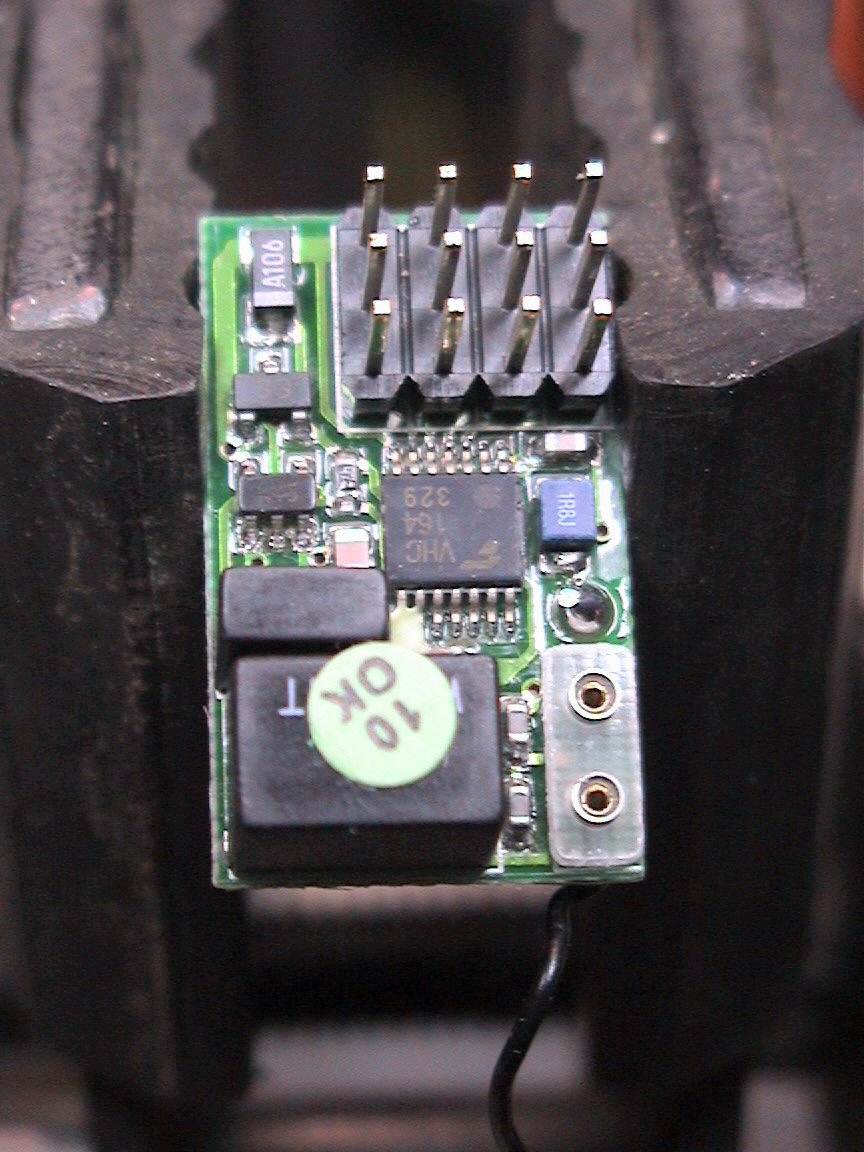
Here's a few pictures that show the 4 channel GWS
receiver PCB and parts. The decoder chip is in the center (one with many
legs). The last picture below show you the required connections for
obtaining 4 additional receiver channels (#5-8)
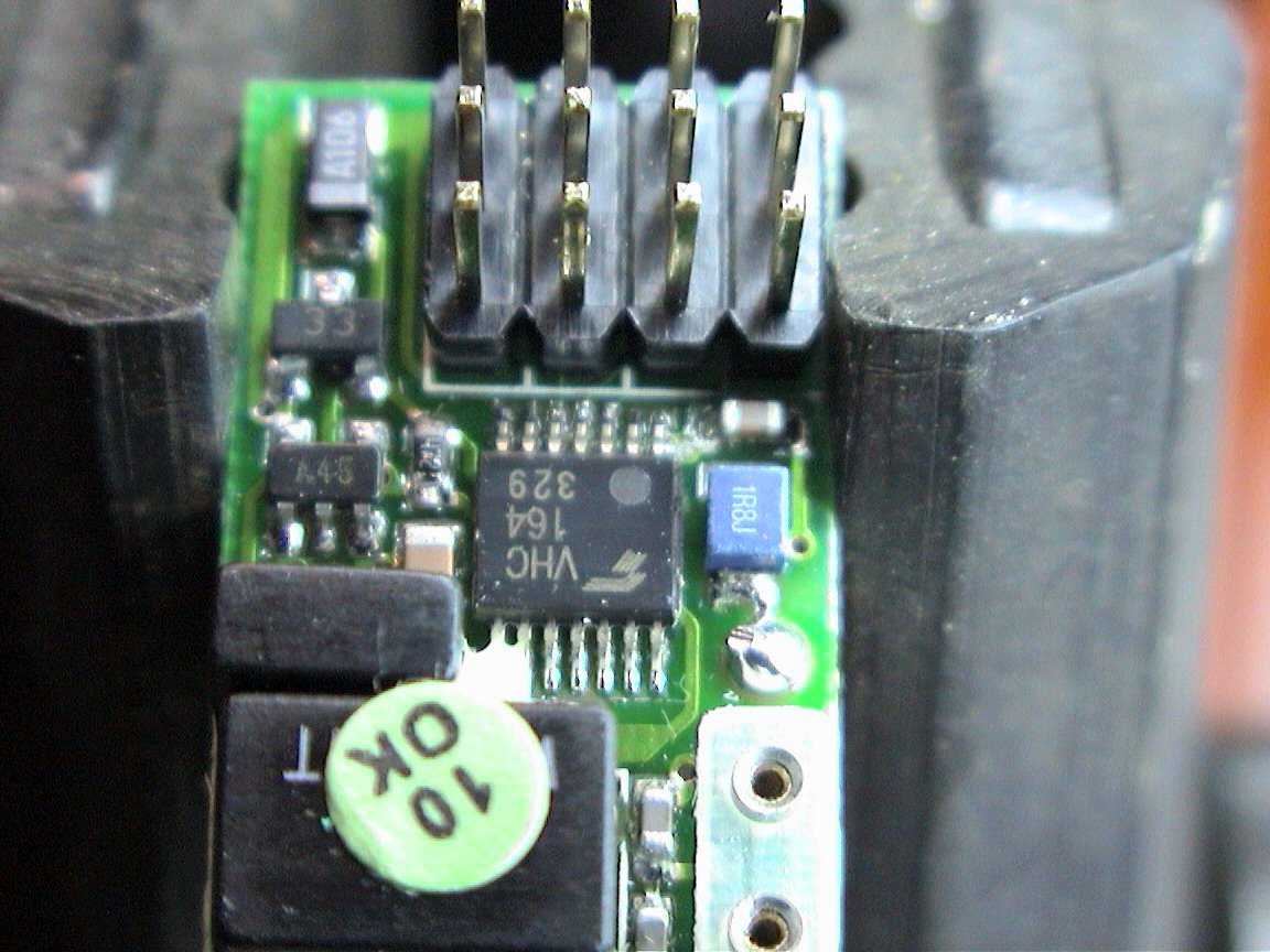

NOTE: Notice that on the
last picture (channel 5 and 8 are noted) the figure only shows Channel
5 and Channel 8. The two pins between these are Channels 6 and 7
respectively (left to right).
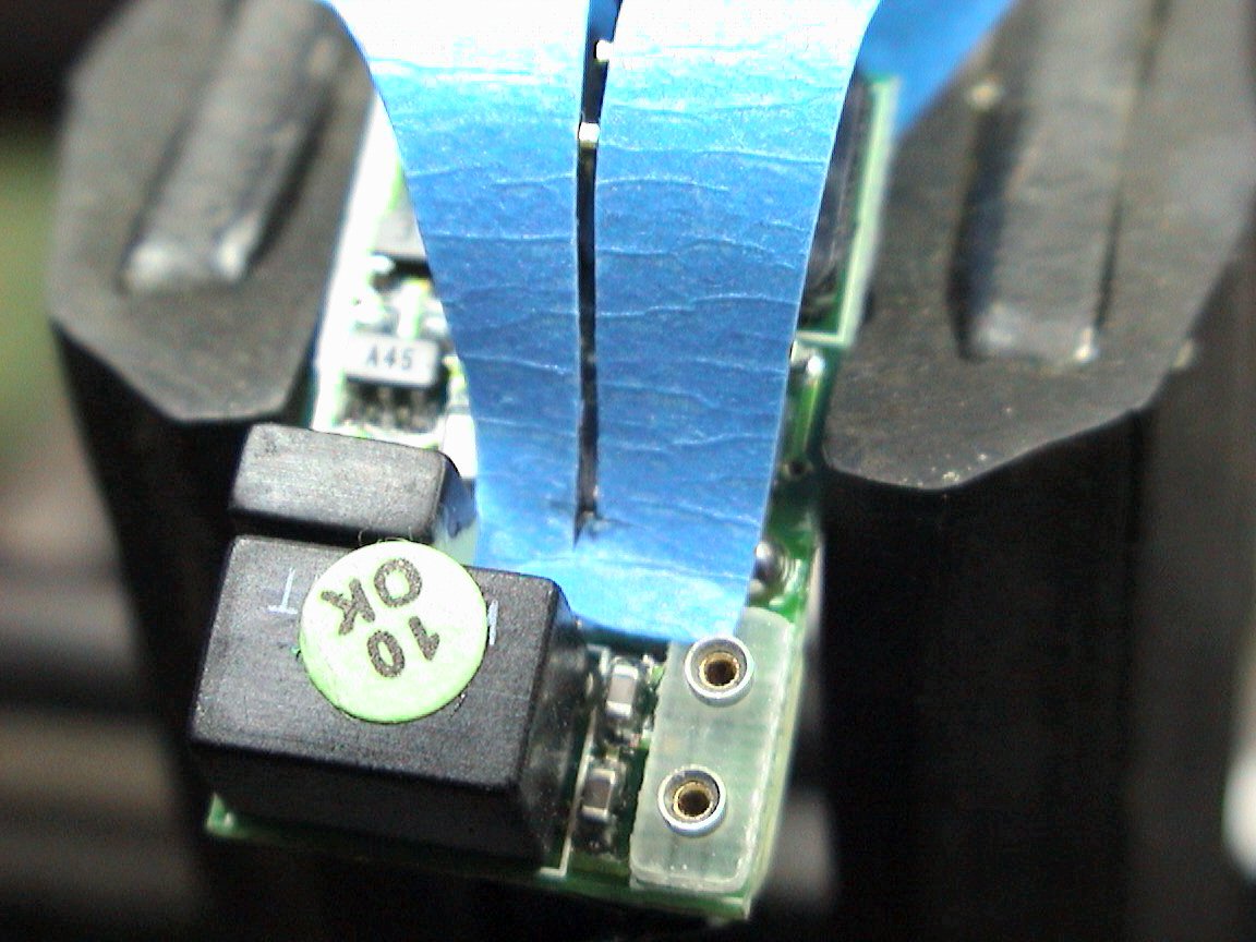
Cut a thin strip out of a
strip of masking tape (about same width as solder land). Lay
masking tape over chip pads such that the pad you want to solder to
(and only this pad) is exposed via the slit.
 First, tin connecting wire, then quickly heat while applying to
exposed solder land on the decoder chip. Masking tape and slit
stops jump-overs (i.e. shorts) when soldering fine pitch lands.
First, tin connecting wire, then quickly heat while applying to
exposed solder land on the decoder chip. Masking tape and slit
stops jump-overs (i.e. shorts) when soldering fine pitch lands.
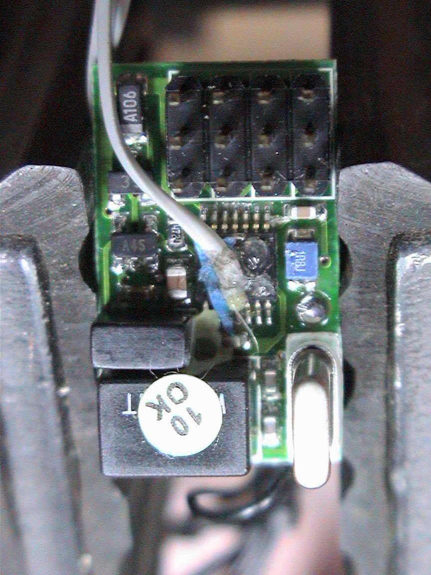 Remove
tape, observe proper connection and then test. Once satisfied,
apply a dab of silicone to support wire/leads (this as shown is
Channel 5, servo signal wire)
Remove
tape, observe proper connection and then test. Once satisfied,
apply a dab of silicone to support wire/leads (this as shown is
Channel 5, servo signal wire)
Solder other wires
for channels 6 through 8 if required, using the same technique of
applying a make-shift "solder mask" made from ordinary masking tape.
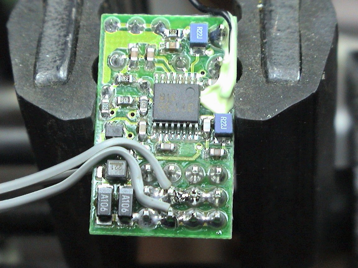
On the bottom of the board, solder the other two required servo
wires (+V and Ground) for each channel you are adding.

Support these wires also with a little dab of
silicone (not shown here in picture but highly recommended)
Testing and Operation Instructions...
1) After making each channel connection you need (#5 through ?), be sure to test
the connection by applying the output of this wire to a spare servo's signal
lead (you'll also need to apply power and ground wires to servo to test
properly). After testing each connection, you can secure each wire to the
PCB with silicone or like.
Additional Notes...
1) ...more coming soon

Earthmen
Productions
© Dec-00-Mar-12
