


 03/30/2012 03/30/2012

Earthmen
Productions
© Dec-00-Mar-12
|
|
Updated:
July 17, 2013
HOW TO MODIFY A SERVO FOR 360 DEGREES OF MOTION
R/C Servos can be modified for 360 degree continuous rotation by
following the simple steps below. Servo designs vary so the pictures
below might not match that of your servo. Basically, what you
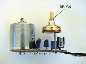
are looking to do is locate the feedback potentiometer (5K Pot. shown
below in picture) and replace this with static (non-varying)
resistors. After this modification, the servo will only be still
(no motion) if and only when the controlling stick/slider on the transmitter is
centered. Move the stick/slider to the right, the servo rotates
to the right, move the stick/slider to the left, the servo rotates to
the left, center the stick/slider, the motor stops moving (and holds
its position).
 |
Step 1
Remove any control horn you have attached to your servo.
Open up your servo. In some cases you would remove the four screws on the bottom of the servo and take off the
bottom plate. With a small screwdriver, carefully
pry out the PC board motor control unit from the plastic case. It
will be tight so go slowly.
Once the motor unit is removed from the casing, you will need to
de-solder the 5K feedback pot and replace it with a couple of
resistors. If there are surface mount parts on the printed circuit
board, be careful not to loosen them when de-soldering the 5K pot. |
 |
Step 2
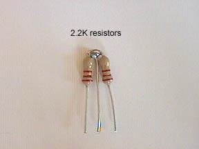
Use two 2.2 K resistors soldered together as a replacement
for the 3 terminal potentiometer (2.7 K resistors should also
work).
By replacing the pot with the two resistors, it will keep the
feedback loop of the servo mechanism at the "centered" value. |
 |
Step 3
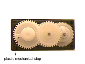
Remove the top cover of the servo to expose the gear box. Slide
off the gear with the plastic mechanical stop on it and file it
off. I used a X-acto knife to shave off the plastic. Replace the
gear and make sure everything rotates smoothly.
Reassemble the servo and test it with your R/C gear. It should continuously rotate forward or
reverse when you output a pulse width not equal to 1.5ms (anything
but center stick).
|
Earthmen
Productions
© Dec-00-Mar-12

|
|